

(UART) universal asynchronous receiver-transmitter

 Advantages


- The idle, no data state is high-voltage, or powered.
- Logic low start bit, data bits, possibly a parity bit and one or more stop bits.
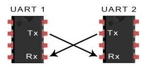
- UARTs transmit data asynchronously, which means there is no clock signal to synchronize the output of bits from the transmitting UART to the sampling of bits by the receiving UART.
- Instead of a clock signal, the transmitting UART adds start and stop bits to the data packet being transferred.
- When the receiving UART detects a start bit, it starts to read the incoming bits at a specific frequency known as the baud rate. Baud rate is a measure of the speed of data transfer, expressed in bits per second (bps). Both UARTs must operate at about the same baud rate. The baud rate between the transmitting and receiving UARTs can only differ by about 10% before the timing of bits gets too far off.
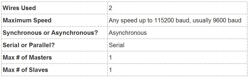
- Only uses two wires
- No clock signal is necessary
- Has a parity bit to allow for error checking
- The structure of the data packet can be changed as long as both sides are set up for it
- Well documented and widely used method
- The size of the data frame is limited to a maximum of 9 bits
- Doesn’t support multiple slave or multiple master systems
- The baud rates of each UART must be within 10% of each other
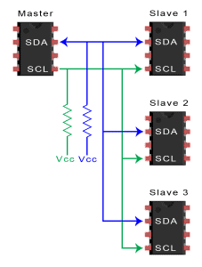
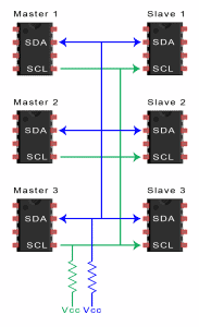
- I2C, you can connect multiple slaves to a single master (like SPI) and you can have multiple masters controlling single, or multiple slaves.
- More then one microcontrollers can logging data to a single memory card or displaying text to a single LCD.
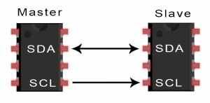
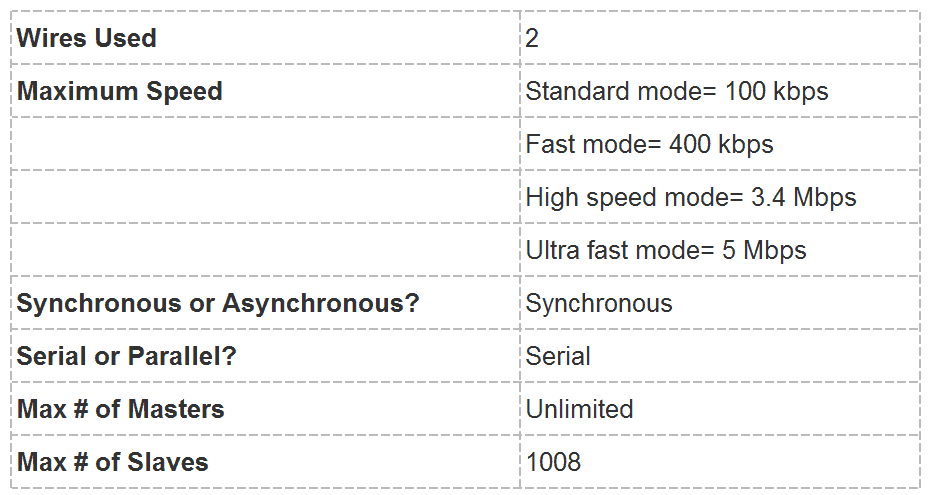
- I2C only uses two wires to transmit data between devices:
SDA (Serial Data) – The line for the master and slave to send and receive data.
SCL (Serial Clock) – The line that carries the clock signal.
- I2C is synchronous, so the output of bits is synchronized to the sampling of bits by a clock signal shared between the master and the slave. The clock signal is always controlled by the master.
I2C terminology
Transmitter
This is the device that transmits data to the bus
This is the device that transmits data to the bus
Receiver
This is the device that receives data from the bus
This is the device that receives data from the bus
Master
This is the device that generates clock, starts communication, sends I2C commands and stops communication
This is the device that generates clock, starts communication, sends I2C commands and stops communication
Slave
This is the device that listens to the bus and is addressed by the master
This is the device that listens to the bus and is addressed by the master
Multi-master
I2C can have more than one master and each can send commands
I2C can have more than one master and each can send commands
Arbitration
A process to determine which of the masters on the bus can use it when more masters need to use the bus
A process to determine which of the masters on the bus can use it when more masters need to use the bus
- If for some reason two masters initiate I2C command at the same time, the arbitration procedure determines which master wins and can continue with the command.
- Arbitration is performed on the SDA signal while the SCL signal is high.
- Each master checks if the SDA signal on the bus corresponds to the generated SDA signal. If the SDA signal on the bus is low but it should be high, then this master has lost arbitration.
- Master I2C device that has lost arbitration can generate SCL pulses until the byte ends and must then release the bus and go into slave mode.
Synchronization
A process to synchronize clocks of two or more devices
A process to synchronize clocks of two or more devices
ACK/NACK Bit: Each frame in a message is followed by an acknowledge/no-acknowledge bit. If an address frame or data frame was successfully received, an ACK bit is returned to the sender from the receiving device.
Bus Signals
Both signals (SCL and SDA) are bidirectional.bus is free, both lines are high. All devices on the bus must have open-collector or open-drain pins. capacitance does not exceed 400 pF. Because logical 1 level depends on the supply voltage, there is no standard bus voltage.
Serial Data Transfer
For each clock pulse one bit of data is transferred. The SDA signal can only change when the SCL signal is low – when the clock is high the data should be stable.
Start and Stop Condition
Each I2C command initiated by master device starts with a START condition and ends with a STOP condition. For both conditions SCL has to be high. A high to low transition of SDA is considered as START and a low to high transition as STOP.
After the Start condition the bus is considered as busy and can be used by another master only after a Stop condition is detected.
CLOCK SYNCHRONIZATION AND HANDSHAKING
Slave devices that need some time to process received byte or are not ready yet to send the next byte, can pull the clock low to signal to the master that it should wait. Once the clock is released the master can proceed with the next byte.
COMMUNICATION WITH 7-BIT I2C ADDRESSES
- Each slave device on the bus should have a unique 7-bit address.
- The communication starts with the Start condition, followed by the 7-bit slave address and the data direction bit.
- direction bit 0 then the master will write to the slave device. Otherwise, if the data direction bit is 1, the master will read from slave device.
- After the slave address and the data direction is sent, the master can continue with reading or writing. The communication is ended with the Stop condition which also signals that the I2C bus is free.
the master only needs to read from the slave device then it simply sends the I2C address with the R/W bit set to read. After this the master device starts reading the data.
7 bits for I2C addresses allow only 127 different addresses where only 112 can actually be used. Some I2C devices on the board, despite address pins, have the same address.
10-bit addressing – supports up to 1024 I2C addresses
Single Master Multiple Slave Multi Master Multiple Slave
Advantages:
- Only uses two wires, Supports multiple masters and multiple slaves
- ACK/NACK bit gives confirmation that each frame is transferred successfully
- Well known and widely used protocol
Disadvantage:
- Slower data transfer rate than SPI
- The size of the data frame is limited to 8 bits
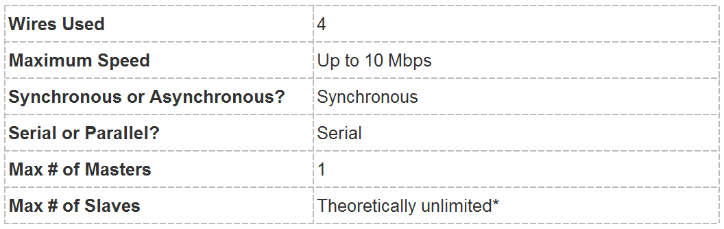
Serial Peripheral Interface (SPI)
- SPI is a common communication protocol used by many different devices.
- One unique benefit of SPI is the fact that data can be transferred without interruption. Any number of bits can be sent or received in a continuous stream.
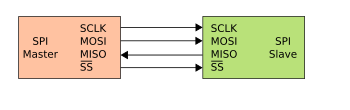
- The simplest configuration of SPI is a single master, single slave system, but one master can control more than one slave
CLK: Serial Clock. Controlled by the master device. A new data bit is shifted out with each clock cycle.
SSN: Slave Select (the "N" identifies it as an active-low signal). Controlled by the master device. An active slave-select line indicates that the master is sending data to or requesting data from the corresponding slave device.
MOSI: Master Out ⇒ Slave In. Data leaves the master device and enters the slave device. MOSI lines on chip A are connected to MOSI lines on chip B.
MISO: Master In ⇐ Slave Out. Data leaves the slave device and enters the master device (or another slave, in a daisy-chain configuration; see the next section). MISO lines on chip A are connected to MISO lines on chip B.
CPOL: Clock Polarity. This governs the initial logic state of the clock signal.
CPHA: Clock Phase. This governs the relationship between the data transitions and the clock transitions.
| Mode | CPOL | CPHA | DATA |
|---|---|---|---|
| 0 | 0 | 0 | Data is sampled at the leading rising edge of the clock |
| 1 | 1 | 0 | Data is sampled at the leading falling edge of the clock |
| 2 | 0 | 1 | Data sampled at on the trailing falling edge of clock |
| 3 | 1 | 1 | Data sampled on the trailing rising edge of clock |
Clock:
- SPI communication is always initiated by the master since the master configures and generates the clock signal.
- The clock signal in SPI can be modified using the properties of clock polarity and clock phase. this define when the bits are output and when they are sampled.
- Clock polarity can be set by the master to allow for bits to be output and sampled on either the rising or falling edge of the clock cycle.
- Clock phase can be set for output and sampling to occur on either the first edge or second edge of the clock cycle, regardless of whether it is rising or falling.
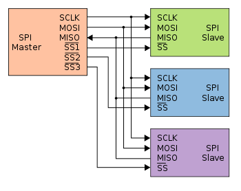
- The master can choose which slave it wants to talk to by setting the slave’s CS/SS line to a low voltage level. In the idle, non-transmitting state, the slave select line is kept at a high voltage level.
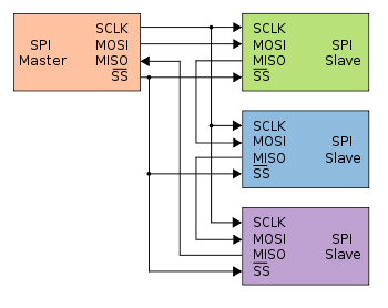
- There are two ways to connect multiple slaves to the master. If the master has multiple slave select pins, the slaves can be wired in parallel called daisy-chaining.
Daisy-chained SPI bus: master and cooperative slaves
Clock transitions govern the shifting and sampling of data. SPI has four modes (0,1,2,3) that correspond to the four possible clocking configurations.
Advantages
- No start and stop bits, so the data can be streamed continuously without interruption
- No complicated slave addressing system like I2C
- Higher data transfer rate than I2C (almost twice as fast)
- Separate MISO and MOSI lines, so data can be sent and received at the same time
- Uses four wires
- No acknowledgement that the data has been successfully received
- No form of error checking like the parity bit in UART
- Only allows for a single master
- The communications must be well-defined in advance (you can't send random amounts of data whenever you want)
- It usually requires separate SS lines to each slave, which can be problematic if numerous slaves are needed.

